
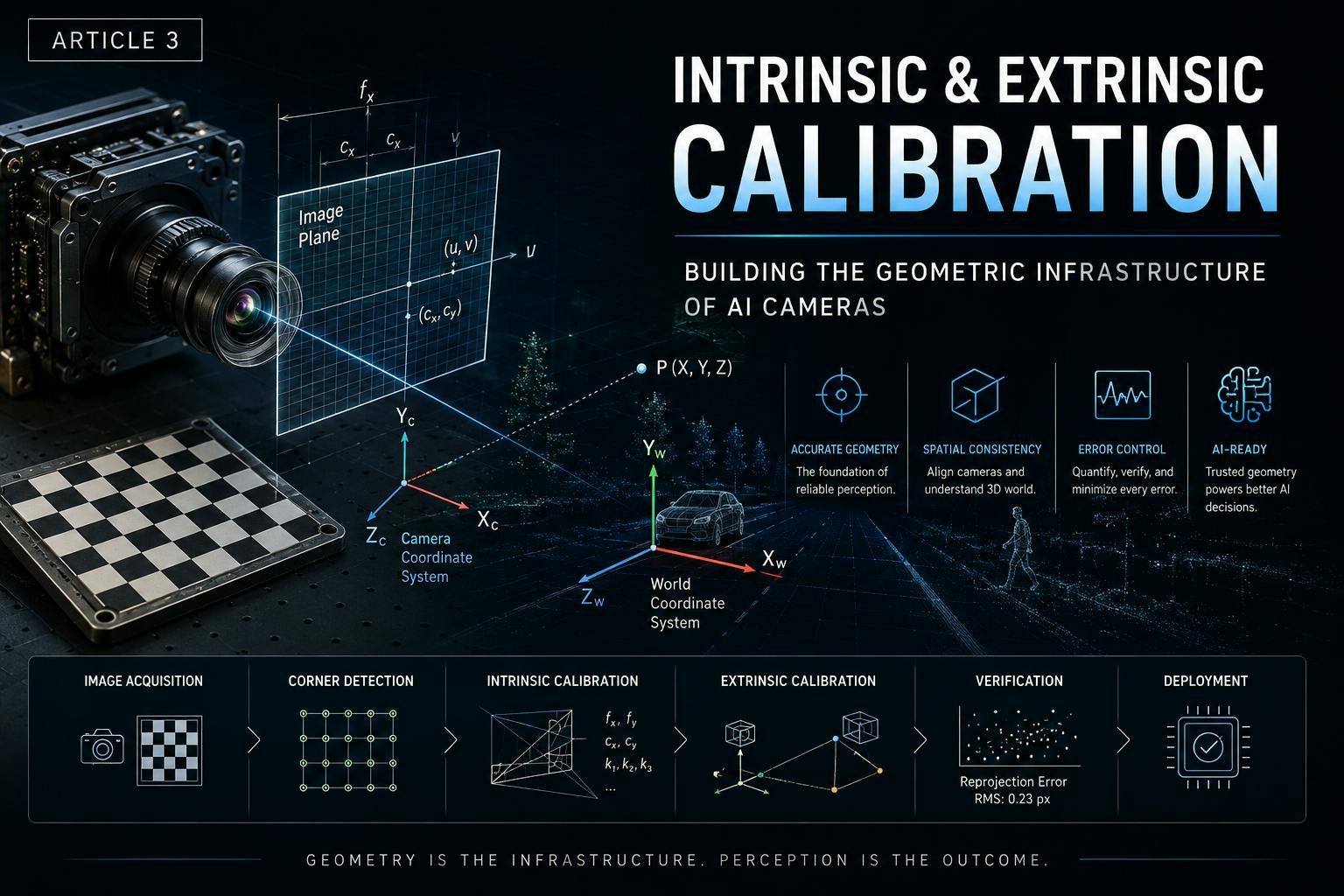
Calibration is the Bridge of Trust Between Hardware and AI In image engineering practice, a common misconception is viewing "Geometric Calibration" purely as a software post-processing task. Many believe that once the hardware team assembles the camera and outputs an image, the remaining distortion correction and spatial positioning can be left entirely to software algorithms. However, in the harsh environment of fleet safety camera systems, this mindset often leads to disastrous consequences. Figure 1: The system value of geometric calibration. Calibration is not the end goal, but the critical bridge connecting camera hardware physics to final AI decisions. Any geometric error uncorrected by calibration will propagate and amplify along this chain. (Image Source: AI-assisted generation)Why Calibration Matters: System Value over Formula Value Without precise geometric calibration, all downstream computer vision algorithms inherit systematic geometric errors. In modern fleet safety systems, features like ADAS, Driver Monitoring, 360° Surround View, SLAM, and Object Detection all rely entirely on accurate calibration. The goal of calibration is not to yield a Matrix, but to guarantee System Accuracy. Engineers must ensure geometric consistency across the entire signal chain: Image → Measurement → Perception → AI. Take Forward Collision Warning (FCW) as an example: if the focal length (fx) in the intrinsic matrix is overestimated by 5%, the system will perceive the vehicle ahead as being further away than it actually is, thereby delaying the warning—a potentially fatal error at highway speeds. For Driver Monitoring Systems, if the principal point offset of the driver-facing lens is uncalibrated, the facial recognition model will generate systematic false negatives in the peripheral regions of the image, leading to missed detections of distracted driving. Article 1: Component Selection discusses selecting glass-plastic hybrid ultra-wide-angle lenses for extreme temperatures and broad fields of view. Article 2: Lab Build-up & Management defines the IQ Lab as a high-precision Measurement System, ensuring that each measurement has high Repeatability, Reproducibility, and Traceability through rigorous measurement strategies, capability matrices, and Golden Sample lifecycle management. The core mission of Article 3: Intrinsic & Extrinsic Calibration is to translate the physical data from this trusted measurement system precisely into mathematical models. Modern fleet safety systems rely heavily on edge AI for real-time inference. When the system needs to determine the distance of a vehicle ahead to trigger a collision warning, or track a pedestrian's trajectory in a lateral blind spot, the foundation upon which the AI model relies is the camera's ability to understand 3D physical space. In a dual-optical architecture that combines a wide-angle and a longer-focal-length lens, precise stereo calibration preserves both scene context and distant detail. If focal-length estimation contains a small error, or edge distortion in the ultra-wide lens is modeled incorrectly, those errors amplify during spatial projection and can cause depth-estimation failures or stitched-image discontinuities. Therefore, geometric calibration is not just a mathematical problem; it is rigorous systems engineering. It requires engineers to deeply understand the physical causes of optical distortion, design highly repeatable lab capture workflows, and seamlessly pass precise calibration matrices downstream to the ISP (Image Signal Processor) and AI algorithms. Starting from basic projective geometry, this article examines the practical calibration of camera intrinsics and extrinsics and shows how globally consistent spatial awareness can be established in complex 360° multi-camera systems. The Geometric Foundation of Camera Imaging For a camera to understand the 3D world, the compression of 3D space into a 2D image must first be understood. Mathematically, this process is described by "Projective Geometry." The Pinhole Camera Model and Homogeneous Coordinates The Pinhole Camera Model is the starting point for all camera geometric calibration. In this ideal model, light rays from the 3D space pass through an infinitely small hole (the optical center) and project onto the sensor plane behind it. Figure 2: Pinhole Camera Model — Coordinate System Transformation. The three coordinate systems from left to right are: World Coordinate System P(X, Y, Z), Camera Coordinate System Pc(Xc, Yc, Zc), and Pixel Coordinate System p(u, v). The extrinsic matrix [R|t] handles the transformation from world to camera coordinates, while the intrinsic matrix K handles the projection from camera to pixel coordinates. The central projection equation s·[u v 1]ᵀ = K·[R|t]·[X Y Z 1]ᵀ fully describes the projection chain. The bottom panels display the complete structures of the extrinsic matrix (3×3 rotation R + 3×1 translation t) and intrinsic matrix (fx, fy, cx, cy). (Image Source: AI-assisted generation) To elegantly handle translation and projection transformations in matrix operations, engineers typically use Homogeneous Coordinates. In a homogeneous coordinate system, a 3D spatial point (X, Y, Z) is represented as a 4D vector (X, Y, Z, 1). This representation not only unifies rotation and translation into matrix multiplication but also naturally describes points at infinity (by setting the last component to 0), which is crucial for handling perspective phenomena where parallel lines intersect at a vanishing point in the image.Camera Matrices: Physical Meaning of Intrinsics and Extrinsics The camera's projection process can be decomposed into two core matrices: the Extrinsic Matrix and the Intrinsic Matrix. The Extrinsic Matrix transforms points in the world coordinate system into points in the camera coordinate system. It describes the camera's pose in physical space, comprising a 3x3 rotation matrix R (describing pitch, yaw, and roll) and a 3x1 translation vector t (describing the 3D position of the camera's optical center in the world). In fleet safety systems, extrinsics determine the installation angle of the front camera relative to the vehicle's centerline, or the height of a side camera relative to the ground. The Intrinsic Matrix (usually denoted as K) projects 3D points from the camera coordinate system onto the 2D pixel coordinate system. It is a 3x3 upper triangular matrix encapsulating the camera's internal optical and photoelectric properties: Focal Length (fx and fy): In the mathematical model, focal length is usually expressed in pixels. It reflects the proportional relationship between the sensor's physical pixel size and the lens's equivalent focal length. In dual-lens modules, road-facing and driver-facing ultra-wide lenses often have materially different focal lengths because their FOV and resolution targets differ. In high-resolution applications, focal-length precision directly affects the calculation of a distant object's pixel size and, in turn, AI distance-estimation accuracy. Measurement and calibration limits should therefore be defined from the system's detection range, output resolution, and task requirements. Principal Point (cx and cy): The principal point is the intersection of the optical axis and the image plane, ideally located at the image's geometric center. However, due to mechanical tolerances in lens assembly and slight sensor placement offsets, the actual principal point usually deviates from the center. The wide-angle and longer-focal-length lenses in a dual-optical system must each be calibrated before stable fusion can occur in a shared virtual space. High-performance edge processors can execute principal-point alignment, geometric mapping, and multi-view fusion on device. Skew: Describes the non-orthogonality of the pixel array. In modern sensors manufactured with high-precision semiconductor processes, this value is safely assumed to be 0. Matrix Type Mathematical Symbol Physical Meaning Influencing Factors System Applications Intrinsic Matrix K (fx, fy, cx, cy) Internal optical projection relationship Lens focal length, pixel size, assembly tolerance Distance estimation, distortion correction, FOV calculation Extrinsic Matrix [R | t] Camera pose in space Mounting position, bracket angle, vehicle vibration Multi-camera stitching, lane line world coordinate transformation Why Precise Calibration is Crucial for Edge AI In fleet safety applications, minor geometric errors are significantly amplified by algorithms. For example, when the front camera executes Forward Collision Warning (FCW), the AI model estimates relative distance and Time to Collision (TTC) based on changes in the vehicle's pixel size in the image. If the focal length (fx) in the intrinsic matrix is overestimated by 5%, the system perceives the vehicle ahead as being further away, delaying the warning—which can be fatal at high speeds. A dual-optical architecture commonly uses a wide-angle lens to capture the complete scene and a longer-focal-length lens to preserve distant-object detail. Because the two lenses differ in image scale and FOV, precise intrinsic calibration and cross-camera geometric mapping are required for reliable multi-view fusion. When a system simultaneously performs distance estimation, object tracking, driver monitoring, and collision-risk analysis, geometric calibration is a shared and indispensable input foundation. Similarly, in 360° multi-camera systems, a 1-degree calibration error in the side camera's extrinsic matrix (specifically the rotation matrix R) translates to a spatial misalignment of nearly 17 cm at a blind spot boundary 10 meters away. This misalignment causes tracked pedestrian trajectories to break across cameras, resulting in false alarms or missed detections. Calibration Accuracy Budget: Error Propagation Chain Analysis Precise calibration is not just about "getting a set of numbers"; it is about understanding how errors propagate and amplify throughout the system. A senior hardware engineer must be able to establish a Calibration Accuracy Budget, tracking the impact of every error source on the final AI output. Figure 4: Calibration Accuracy Budget Error Propagation Chain. The six nodes are: Lens Distortion → Corner Detection Error → Intrinsic Error → Extrinsic Error → Depth Error → Perception Error. Errors at each stage accumulate and amplify downstream, ultimately affecting the system accuracy of FCW / LDW / BSD. (Image Source: AI-assisted generation)Taking distance estimation as an example, the error propagation chain is as follows: Error Source Typical Magnitude Impact on Distance Estimation Checkerboard manufacturing error ±0.05 mm Focal length error 95%. Intrinsic Calibration: Use Zhang's Method to calculate the initial solution, followed by Levenberg-Marquardt (LM) non-linear optimization to solve for focal length, principal point, and distortion coefficients. Extrinsic Calibration: Calculate the Joint [R|t] between cameras, applicable for stereo and multi-camera systems. Verification (Quality Gate): Calculate Reprojection Error; the R&D standard is 1 ms during dual-lens capture Use hardware sync trigger to ensure latency < 1 ms In the mass production environment of fleet cameras, Thermal Drift is the most frequently overlooked yet most impactful failure mode. Many engineers consider the job done after completing calibration at room temperature, ignoring the camera's actual operating conditions in summer parking lots (in-cabin temps reaching 70°C+) or winter freezes (-30°C). Establishing a complete temperature compensation model is the key to ensuring the system maintains geometric accuracy throughout its lifecycle.From Lab to Mass Production: Landing Calibration in Engineering No matter how perfect the mathematical model is, it must ultimately land on the factory production line and in the customer's vehicles. Guiding Factory EOL Testing and Golden Samples During the R&D phase (EVT/DVT), the IQ Lab establishes a batch of perfectly performing "Golden Samples" through rigorous calibration workflows. According to the Golden Sample lifecycle management framework described in Article 2: Lab Build-up & Management, these samples must undergo repeated lab measurements to confirm that their IQ metrics (MTF, SNR, color deviation) are at the center of the normal distribution, following a complete closed loop: "Calibration Baseline → Periodic Verification → Equipment Drift Detection → Reference Update → Factory Alignment." The intrinsic matrices and distortion coefficients of these Golden Samples become the baseline for factory End-of-Line (EOL) testing. On the mass production line, due to strict Takt Time limits, it is impossible to perform a 20-minute Zhang's Method calibration on every single camera. Instead, factories design simplified calibration stations where the camera only needs to capture 1 to 3 target images at specific angles. The test software rapidly extracts feature points from the center and corners, calculates simplified intrinsics, and compares them against the Golden Sample baseline. If the focal length or principal point offset exceeds the set tolerance threshold, the system determines that severe tilt or decentering occurred during the Active Alignment process, and the module is rejected. In fleet camera mass production, this simplified EOL calibration verification ensures that every shipped camera meets basic geometric requirements. A typical EOL calibration station includes a fixed checkerboard target and a high-speed camera interface; the entire test process (including image capture, feature extraction, parameter calculation, and baseline comparison) is usually completed within 30-60 seconds to meet Takt Time requirements. Coping with Extreme Environments: Thermal Drift and Compensation Fleet cameras must operate in extreme temperatures ranging from -40°C to 85°C. The laws of physics dictate that even glass-plastic hybrid lenses with Athermalization designs will experience minor drifts in focal length and principal point as temperature changes. If the AI algorithm always uses the intrinsic matrix calibrated at room temperature (25°C), distance estimation will suffer systematic bias in the 85°C heat. To solve this, senior hardware engineers perform "Dynamic Temperature Calibration" in environmental test chambers. By recording intrinsic changes across different temperature steps, a temperature compensation model (usually linear or quadratic polynomial) is established. During actual operation, the camera's SoC reads data from the built-in temperature sensor and dynamically adjusts the intrinsic matrix in real-time, ensuring the edge AI receives absolutely precise geometric inputs regardless of the climate. In engineering practice, temperature compensation models typically use quadratic polynomials to describe the drift patterns of focal length and principal point with temperature (the following is a typical engineering approach, not specific vendor public data): fx(T) = fx_ref + a1 * (T - T_ref) + a2 * (T - T_ref)^2 cy(T) = cy_ref + b1 * (T - T_ref) + b2 * (T - T_ref)^2 Where T_ref = 25°C, and a1, a2, b1, b2 are coefficients obtained through least squares fitting during temperature testing. By design, ensuring that temperature compensation data can be accurately applied to real-time inference in extreme environments is a crucial part of system reliability. Furthermore, good design usually includes a "Cold Start Compensation" mechanism; when the camera boots up in extremely cold environments, the system automatically selects the closest calibration parameter set based on the boot temperature, rather than waiting for the temperature sensor to reach a stable state. Conclusion: Laying the Cornerstone for Mass Production and Reliability Intrinsic & Extrinsic Calibration is by no means a mere mathematical game; it is the critical translation process that turns camera hardware potential into system intelligence. From the theoretical foundation of the pinhole model to the complex polynomials handling ultra-wide distortion; from rigorous checkerboard capture in the lab to pursuing globally consistent Bundle Adjustment in multi-camera systems—every step tests the engineer's wisdom in balancing theoretical depth with practical feasibility. Precise geometric calibration is not just an input for ISP distortion correction; it is the absolute prerequisite for the reliability of edge AI algorithms (like distance estimation, lane tracking, and blind-spot monitoring). It validates the hardware selection logic from Article 1: Component Selection and transforms the "high-precision measurement system" established by the IQ Lab in Article 2: Lab Build-up & Management—with its rigorous measurement strategies, capability matrices, and Golden Sample management—into executable mathematical models and code, endowing the entire system with a precise cognitive grasp of 3D space. Dual-lens road and driver-monitoring architectures, wide-angle and longer-focal-length dual-optical architectures, and 360° panoramic-stitching architectures all illustrate how precise calibration supports Forward Collision Warning, driver-state monitoring, and multi-camera spatial fusion. Preserving peripheral accuracy at extreme FOV, establishing stable extrinsics across cameras, and maintaining calibration validity through mass production and full-temperature operation remain central engineering challenges. Even after an ideal calibration matrix is obtained in the lab, the real challenge has only begun: how can every camera on the factory production line consistently achieve the same geometric precision? The next article (Article 4: Factory Testing & AA) examines mass-production technologies, including how Active Alignment reduces mechanical tolerances and how rigorous EOL testing and Statistical Process Control (SPC) help ensure consistent geometric quality for cameras delivered to fleets. Disclaimer The technical perspectives, engineering methodologies, and practical recommendations presented in this article are independent analyses and viewpoints formulated by the author. They are based on years of experience in camera product development, combined with publicly available information (including official websites, public product data, technical whitepapers, academic papers, industry standards, and public product specifications). This article does not compare, recommend, endorse, or promote any specific vendor, product, or trademark. The system contexts and engineering metrics are intended solely to explain general camera geometric-calibration methods and design trade-offs. Unless otherwise noted, all images used in this article are either created by the author, generated with AI assistance, or cited from publicly available information that may be legally used. Where third-party images or data are cited, the source and original origin are indicated in appropriate locations. The content of this article is for technical exchange and educational reference only and does not constitute engineering design, business decision-making, or other professional advice. As technologies, product specifications, and industry best practices may evolve over time, readers should independently evaluate their applicability to actual use cases. References [1] Zhang, Z. "A flexible new technique for camera calibration." IEEE Transactions on Pattern Analysis and Machine Intelligence, vol. 22, no. 11, pp. 1330-1334, Nov 2000. DOI: 10.1109/34.888718. Available: [2] OpenCV Documentation. "Camera Calibration and 3D Reconstruction." OpenCV.org, 2026. Available: [3] Scaramuzza, D., Martinelli, A., & Siegwart, R. "A Toolbox for Easily Calibrating Omnidirectional Cameras." 2006 IEEE/RSJ International Conference on Intelligent Robots and Systems (IROS ), 2006. DOI: 10.1109/IROS.2006.282372. Available: [4] Hartley, R., & Zisserman, A. "Multiple View Geometry in Computer Vision." Cambridge University Press, 2nd Edition, 2004. Available:
Intrinsic and Extrinsic Calibration for Fleet Safety Camera Systems
Full Article
Original Source
Read the full article at Hackernoon →KhanList aggregates and links to publicly available news content. We do not host full articles from third-party sources. Always verify important information with original sources.